In a previous post, we went over the geometry of image formation and learned how a point in 3D gets projected on to the image plane of a camera.
The model we used was based on the pinhole camera model. The only time you use a pinhole camera is probably during an eclipse.
The model of image formation for any real world camera involves a lens.
Have you ever wondered why we attach a lens to our cameras? Does it affect the transformation defining the projection of a 3D points to a corresponding pixel in an image? If yes, how do we model it mathematically?
In this post we will answer the above questions.
Replacing the pinhole by a lens
To generate clear and sharp images the diameter of the aperture (hole) of a pinhole camera should be as small as possible. If we increase the size of the aperture, we know that rays from multiple points of the object would be incident on the same part of the screen creating a blurred image.
On the other hand, if we make the aperture size small, only a small number of photons hit the image sensor. As a result the image is dark and noisy.
So, smaller the aperture of the pinhole camera, more focused is the image but, at the same time, darker and noisier it is.
On the other hand, with a larger aperture, the image sensor receives more photons ( and hence more signal ). This leads to a bright image with only a small amount of noise.
How do we get a sharp image but at the same time capture more light rays to make the image bright?
We replace the pinhole by a lens thus increasing the size of the aperture through which light rays can pass. A lens allows larger number of rays to pass through the hole and because of its optical properties it can also focus them on the screen. This makes the image brighter.
Awesome! So we have bright and sharp, focused image using a lens.
The problem is solved? Right? Not so fast. Nothing comes for free!
Major types of distortion effects and their cause
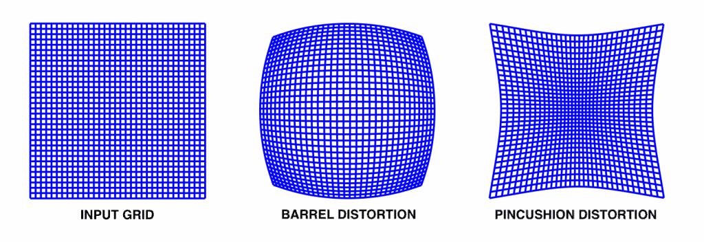
By using a lens we get better quality images but the lens introduces some distortion effects. There are two major types of distortion effects :
- Radial distortion: This type of distortion usually occur due unequal bending of light. The rays bend more near the edges of the lens than the rays near the centre of the lens. Due to radial distortion straight lines in real world appear to be curved in the image. The light ray gets displaced radially inward or outward from its ideal location before hitting the image sensor. There are two type of radial distortion effect
- Barrel distortion effect, which corresponds to negative radial displacement
- Pincushion distortion effect, which corresponds to a positive radial displacement.
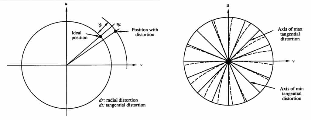
- Tangential distortion: This usually occurs when image screen or sensor is at an angle w.r.t the lens. Thus the image seem to be tilted and stretched.
Based on [1] there are 3 types of distortion depending on the source of distortion, radial distortion, decentering distortion and thin prism distortion. The decentering and thin prism distortion have both, radial and tangential distortion effect.
Now we have a better idea of what types of distortion effects are introduced by a lens, but what does a distorted image look like ? Do we need to worry about the distortion introduced by the lens ? If yes why ? How do we deal with it ?
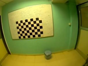
The above figure is an example of distortion effect that a lens can introduce. You can relate figure 3 with figure 1 and say that it is a barrel distortion effect, a type of radial distortion effect. Now if you were asked to find the height of the right door, which two points would you consider ? Things become even more difficult when you are performing SLAM or making some augmented reality application with cameras having high distortion effect in the image.
Representing the lens distortion mathematically
When we try to estimate the 3D points of the real world from an image, we need to consider these distortion effects.
We mathematically model the distortion effect based on the lens properties and combine it with the pinhole camera model that is explained in the previous post of this series. So along with intrinsic and extrinsic parameters discussed in the previous post, we also have distortion coefficients (which mathematically represent the lens distortion), as additional intrinsic parameters.
To consider these distortions in our camera model we modify the pinhole camera model as follows :
(1) 
(2) ![]()
(3) ![]()
(4) ![]()
(5) ![]()
(6) 
(7) 
(8) 
The distCoeffs matrix returned by the calibrateCamera method give us the values of K_1, to K_6, which represent the radial distortion and P_1 , P_2, which represent the tangential distortion. As we know that the above mathematical model representing the lens distortion, includes all the types of distortions, radial distortion, decentering distortion and thin prism distortion, thus the coefficients K_1 to K_6 represent the net radial distortion and P_1 and P_2 represent the net tangential distortion.
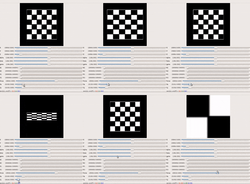
Great ! So in this series of posts on camera calibration we started with geometry of image formation , then we performed camera calibration and discussed the basic theory involved we also discussed the mathematical model of a pin hole camera and finally we discussed lens distortion in this post. With this understanding you can now create your own virtual camera and simulate some interesting effects using OpenCV and Numpy. You can refer to this repository where a a virtual camera is implemented using only Numpy computations. With all the parameters, intrinsic as well as extrinsic, in your hand you can get a better feeling of the effect each parameter of the camera has on the final image you see.
There are several other parameters which you can change using the GUI provided in the repository. It will help you to have a better intuition about effect of various camera parameters.
Removing the distortion using OpenCV
So what do we do after the calibration step ? We got the camera matrix and distortion coefficients in the previous post on camera calibration but how do we use the values ?
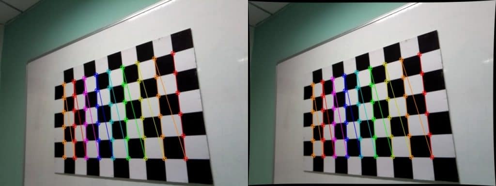
One application is to use the derived distortion coefficients to un-distort the image. Images shown below depict the effect of lens distortion and how it can be removed from the coefficients obtained from camera calibration.
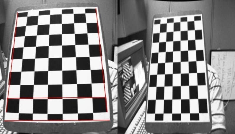
There are three major steps to remove distortion due to lens.
- Perform camera calibration and get the intrinsic camera parameters. This is what we did in the previous post of this series. The intrinsic parameters also include the camera distortion parameters.
- Refine the camera matrix to control the percentage of unwanted pixels in the undistorted image.
- Using the refined camera matrix to undistort the image.
The second step is performed using the getOptimalNewCameraMatrix() method. What does this refined matrix mean and why do we need it ? Refer to the following images, in the right image we see some black pixels near the edges. These occur due to undistortion of the image. Sometimes these black pixels are not desired in the final undistorted image. Thus getOptimalNewCameraMatrix() method returns a refined camera matrix and also the ROI(region of interest) which can be used to crop the image such that all the black pixels are excluded. The percentage of unwanted pixels to be eliminated is controlled by a parameter alpha which is passed as an argument to the getOptimalNewCameraMatrix() method.
It is important to note that sometimes in case of high radial distortions, using the getOptimalNewCameraMatrix() with alpha=0 generates a blank image. This usually happens because the method gets poor estimates for the distortion at the edges. In such cases you need to recalibrate the camera and ensure that more images are taken with different views close to image borders. This way more samples near image border would be available for estimating the distortion, thus improving the estimation.
Python code
# Refining the camera matrix using parameters obtained by calibration
newcameramtx, roi = cv2.getOptimalNewCameraMatrix(mtx, dist, (w,h), 1, (w,h))

# Method 1 to undistort the image
dst = cv2.undistort(img, mtx, dist, None, newcameramtx)

# Method 2 to undistort the image
mapx,mapy=cv2.initUndistortRectifyMap(mtx,dist,None,newcameramtx,(w,h),5)

dst = cv2.remap(img,mapx,mapy,cv2.INTER_LINEAR)

# Displaying the undistorted image
cv2.imshow("undistorted image",dst)
cv2.waitKey(0)
C++ code
cv::Mat dst, map1, map2,new_camera_matrix;
cv::Size imageSize(cv::Size(image.cols,image.rows));

// Refining the camera matrix using parameters obtained by calibration
new_camera_matrix = cv::getOptimalNewCameraMatrix(cameraMatrix, distCoeffs, imageSize, 1, imageSize, 0);

// Method 1 to undistort the image
cv::undistort( frame, dst, new_camera_matrix, distCoeffs, new_camera_matrix );

// Method 2 to undistort the image
cv::initUndistortRectifyMap(cameraMatrix, distCoeffs, cv::Mat(),cv::getOptimalNewCameraMatrix(cameraMatrix, distCoeffs, imageSize, 1, imageSize, 0),imageSize, CV_16SC2, map1, map2);

cv::remap(frame, dst, map1, map2, cv::INTER_LINEAR);

//Displaying the undistorted image
cv::imshow("undistorted image",dst);
cv::waitKey(0);;
References
[1] J. Weng, P. Cohen, and M. Herniou. Camera calibration with distortion models and accuracy
evaluation. IEEE Transactions on Pattern Analysis and Machine Intelligence, 14(10):965–980,
Oct. 1992.
[2] OpenCV documentation for camera calibration.




100K+ Learners
Join Free OpenCV Bootcamp3 Hours of Learning