In this post, we will explain the image formation from a geometrical point of view.
Specifically, we will cover the math behind how a point in 3D gets projected on the image plane.
This post is written with beginners in mind but it is mathematical in nature. That said, all you need to know is matrix multiplication.
The Setup
To understand the problem easily, let’s say you have a camera deployed in a room.
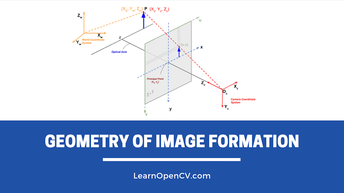
Given a 3D point P in this room, we want to find the pixel coordinates (u, v) of this 3D point in the image taken by the camera.
There are three coordinate systems in play in this setup. Let’s go over them.
1. World Coordinate System
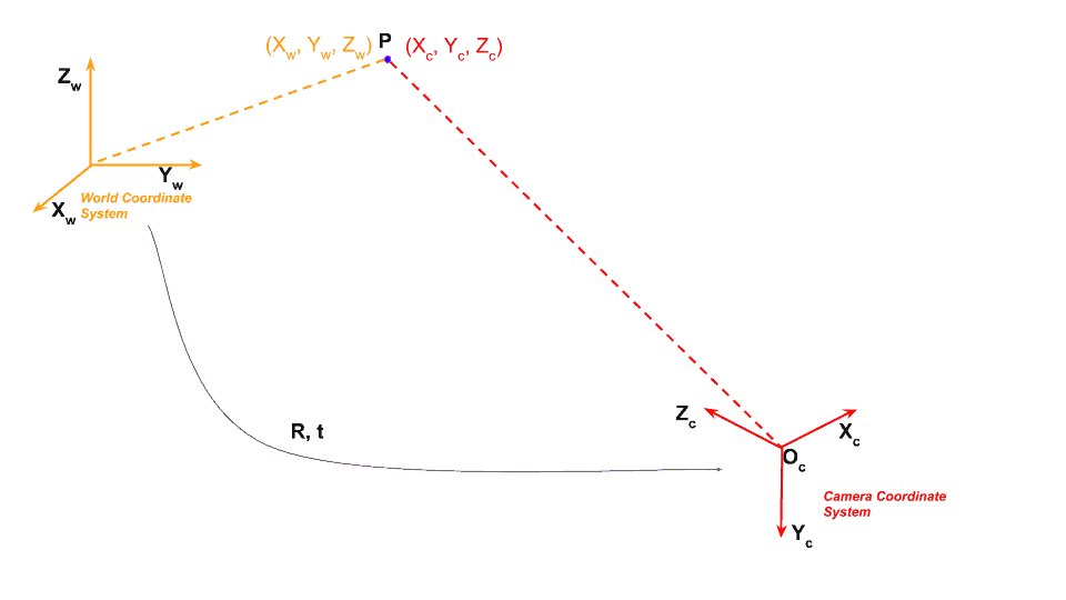
To define locations of points in the room we need to first define a coordinate system for this room. It requires two things
- Origin : We can arbitrarily fix a corner of the room as the origin
 .
. - X, Y, Z axes : We can also define the X and Y axis of the room along the two dimensions on the floor and the Z axis along the vertical wall.
Using the above, we can find the 3D coordinates of any point in this room by measuring its distance from the origin along the X, Y, and Z axes.
This coordinate system attached to the room is referred to as the World Coordinate System. In Figure 1, it is shown using orange colored axes. We will use bold font ( e.g. ![]() ) to show the axis, and regular font to show a coordinate of the point ( e.g.
) to show the axis, and regular font to show a coordinate of the point ( e.g. ![]() ).
).
Let us consider a point P in this room. In the world coordinate system, the coordinates of P are given by ![]() . You can find
. You can find ![]() ,
, ![]() , and
, and ![]() coordinates of this point by simply measuring the distance of this point from the origin along the three axes.
coordinates of this point by simply measuring the distance of this point from the origin along the three axes.
2. Camera Coordinate System
Now, let’s put a camera in this room.
The image of the room will be captured using this camera, and therefore, we are interested in a 3D coordinate system attached to this camera.
If we had put the camera at origin of the room, and align it such that its X, Y, and Z axes aligned with the ![]() ,
,![]() , and
, and ![]() axes of the room, the two coordinate systems would be the same.
axes of the room, the two coordinate systems would be the same.
However, that is an absurd restriction. We would want to put the camera anywhere in the room and it should be able to look anywhere. In such a case, we need to find the relationship between the 3D room (i.e. world) coordinates and the 3D camera coordinates.
Let’s say our camera is located at some arbitrary location ![]() in the room. In technical jargon, we can the camera coordinate is translated by
in the room. In technical jargon, we can the camera coordinate is translated by ![]() with respect to the world coordinates.
with respect to the world coordinates.
The camera may be also looking in some arbitrary direction. In other words, we can say the camera is rotated with respect to the world coordinate system.
Rotation in 3D is captured using three parameters —- you can think of the three parameters as yaw, pitch, and roll. You can also think of it as an axis in 3D ( two parameters ) and an angular rotation about that axis (one parameter).
However, it is often convenient for mathematical manipulation to encode rotation as a 3×3 matrix. Now, you may be thinking that a 3×3 matrix has 9 elements and therefore 9 parameters but rotation has only 3 parameters. That’s true, and that is exactly why any arbitrary 3×3 matrix is not a rotation matrix. Without going into the details, let us for now just know that a rotation matrix has only three degrees of freedom even though it has 9 elements.
Back to our original problem. The world coordinate and the camera coordinates are related by a rotation matrix ![]() and a 3 element translation vector
and a 3 element translation vector ![]()
What does that mean?
It means that point P which had coordinate values ![]() in the world coordinates will have different coordinate values
in the world coordinates will have different coordinate values ![]() in the camera coordinate system. We are representing the camera coordinate system using red color.
in the camera coordinate system. We are representing the camera coordinate system using red color.
The two coordinate values are related by the following equation.
(1) 
Notice that representing rotation as a matrix allowed us to do rotation with a simple matrix multiplication instead of tedious symbol manipulation required in other representations like yaw, pitch, roll. I hope this helps you appreciate why we represent rotations as a matrix.
Sometimes the expression above is written in a more compact form. The 3×1 translation vector is appended as a column at the end of the 3×3 rotation matrix to obtain a 3×4 matrix called the Extrinsic Matrix.
(2) 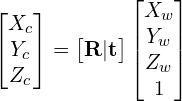
where, the extrinsic matrix ![]() is given by
is given by
(3) ![]()
Homogeneous coordinates : In projective geometry, we often work with a funny representation of coordinates where an extra dimension is appended to the coordinates. A 3D point ![]() in cartesian coordinates can written as
in cartesian coordinates can written as ![]() in homogenous coordinates. More generally, a point in homogenous coordinate
in homogenous coordinates. More generally, a point in homogenous coordinate ![]() is the same as the point
is the same as the point ![]() in cartesian coordinates. Homogenous coordinates allow us to represent infinite quantities using finite numbers. For example, the point at infinity can be represented as
in cartesian coordinates. Homogenous coordinates allow us to represent infinite quantities using finite numbers. For example, the point at infinity can be represented as ![]() in homogenous coordinates. You may notice that we have used homogenous coordinates in Equation 2 to represent the world coordinates.
in homogenous coordinates. You may notice that we have used homogenous coordinates in Equation 2 to represent the world coordinates.
3. Image Coordinate System
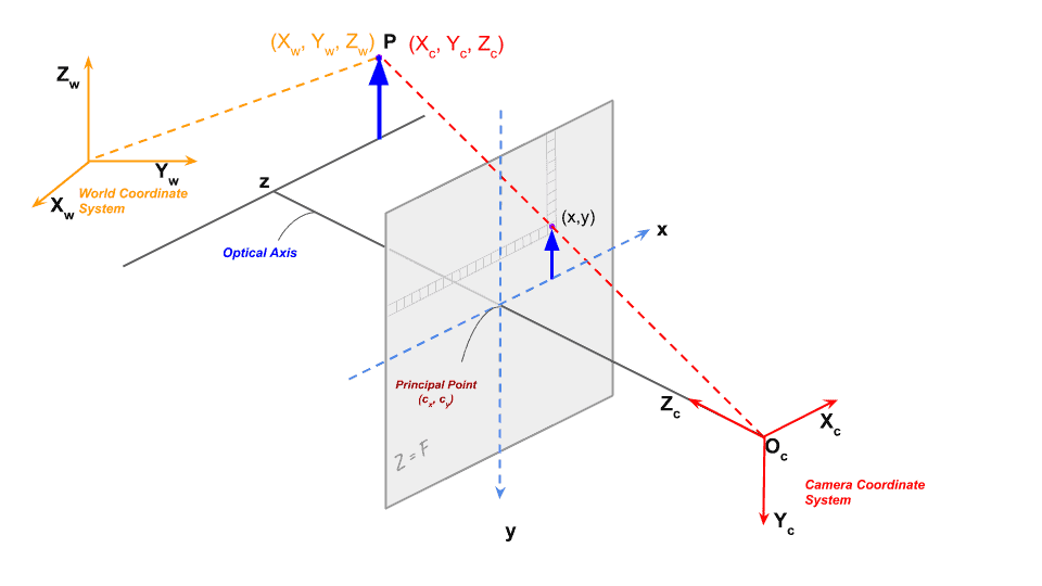
Once we get a point in 3D coordinate system of the camera by applying a rotation and translation to the points world coordinates, we are in a position to project the point on the image plane to obtain a location of the point in the image.
In the image above, we are looking at a point P with coordinates ![]() in the camera coordinate system. Just a reminder, if we did not know the coordinates of this point in the camera coordinate system, we could transform its world coordinates using the Extrinsic Matrix to obtain the coordinates in the camera coordinate system using Equation 2.
in the camera coordinate system. Just a reminder, if we did not know the coordinates of this point in the camera coordinate system, we could transform its world coordinates using the Extrinsic Matrix to obtain the coordinates in the camera coordinate system using Equation 2.
Figure 2, shows the camera projection in case of a simple pin hole camera.
The optical center (pin hole) is represented using ![]() . In reality an inverted image of the point is formed on the image plane. For mathematical convenience, we simply do all the calculations as if the image plane is in front of the optical center because the image read out from the sensor can be trivially rotated by 180 degrees to compensate for the inversion. In practice even this is not required. Reader Olaf Peters pointed out in the comments section — “It is even simpler: a real cameras sensor just reads out from the most bottom row in reverse order (from right to left), and then from bottom to top for each row. By this method the image is automatically formed upright and left and right are in correct order. So in practice there is no need to rotate the image anymore.”
. In reality an inverted image of the point is formed on the image plane. For mathematical convenience, we simply do all the calculations as if the image plane is in front of the optical center because the image read out from the sensor can be trivially rotated by 180 degrees to compensate for the inversion. In practice even this is not required. Reader Olaf Peters pointed out in the comments section — “It is even simpler: a real cameras sensor just reads out from the most bottom row in reverse order (from right to left), and then from bottom to top for each row. By this method the image is automatically formed upright and left and right are in correct order. So in practice there is no need to rotate the image anymore.”
The image plane is placed at a distance ![]() (focal length) from the optical center.
(focal length) from the optical center.
Using high school geometry ( similar triangles ), we can show the project image ![]() of the 3D point
of the 3D point ![]() is given by.
is given by.
(4) 
The above two equations can be rewritten in matrix form as follows
(5) 
The matrix ![]() shown below is called the Intrinsic Matrix and contains the intrinsic parameters of the camera.
shown below is called the Intrinsic Matrix and contains the intrinsic parameters of the camera.
(6) 
The above simple matrix shows only the focal length.
However, the pixels in the image sensor may not be square, and so we may have two different focal lengths ![]() and
and ![]() .
.
The optical center ![]() of the camera may not coincide with the center of the image coordinate system.
of the camera may not coincide with the center of the image coordinate system.
In addition, there may be a small skew ![]() between the x and y axes of the camera sensor.
between the x and y axes of the camera sensor.
Taking all the above into account, the camera matrix can be re-written as.
(7) 
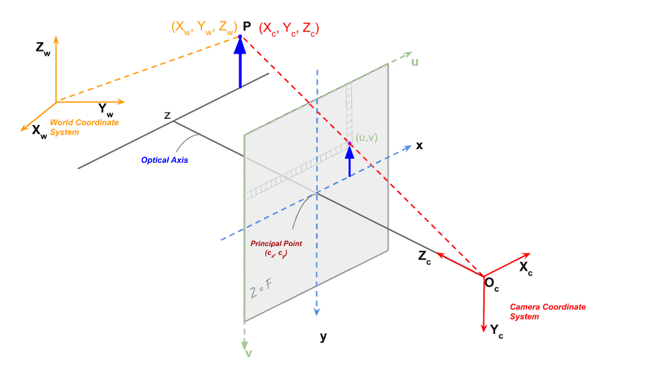
However, in the above equation, the x and y pixel coordinates are with respect to the center of the image. However, while working with images the origin is at the top left corner of the image.
Let’s represent the image coordinates by ![]() .
.
(8) 
where,
(9) 
Summary
Projecting a 3D point in world coordinate system to camera pixel coordinates is done in three steps.
- The 3D point is transformed from world coordinates to camera coordinates using the Extrinsic Matrix which consists of the Rotation and translation between the two coordinate systems.
- The new 3D point in camera coordinate system is projected onto the image plane using the Intrinsic Matrix which consists of internal camera parameters like the focal length, optical center, etc.
In the next post in this series, we will learn about camera calibration and how do perform it using OpenCV’s function.







100K+ Learners
Join Free OpenCV Bootcamp3 Hours of Learning