We all remember those awesome childhood days when we use to go to amusement parks or county fairs. One of my favorite elements of these amusement parks was the fun-house mirror room.
Funny mirrors are not plane mirrors but a combination of convex/concave reflective surfaces that produce distortion effects that look funny as we move in front of these mirrors.
In this post, we will learn to create our own funny mirrors using OpenCV.
We can see how the kid in the above video is enjoying different funny mirrors. We all would like to have such fun right ? But for that we have to go to an amusement park or a fun house mirror room.
Well ! now you can enjoy such fun effects at your home, without going to a fun house mirror room. In this post, we will learn how to make a digital version of these funny mirrors using OpenCV. This post’s code is inspired by my recent projects FunMirrors and VirtualCam.
The main motivation for this post is to encourage our readers to learn fundamental concepts like geometry of image formation, camera projection matrix, intrinsic and extrinsic parameters of a camera.
By the end of this post you will be able to appreciate the fact that one can create something really interesting after having a clear idea of fundamental concepts and theory.
Theory of Image Formation
To understand the theory of how a 3D point in the world is projected into the image frame of a camera, read these posts on geometry of image formation and camera calibration.
Now we know that a 3D point ![]() in the world coordinates is mapped to its corresponding pixel coordinates
in the world coordinates is mapped to its corresponding pixel coordinates ![]() based on the following equation, where P is the camera projection matrix.
based on the following equation, where P is the camera projection matrix.
![\[ \begin{bmatrix} u' \\ v' \\ z' \\ \end{bmatrix} = \textbf{P}\begin{bmatrix} X{w} \\ Y{w} \\ z{w} \\ 1 \\ \end{bmatrix} \]](https://learnopencv.com/wp-content/ql-cache/quicklatex.com-a7f186713801844be2f20b0503d23f95_l3.png)
![]()
![]()
How does it work ?
The entire project can be divided into three major steps :
- Create a virtual camera.
- Define a 3D surface (the mirror surface) and project it into the virtual camera using a suitable value of projection matrix.
- Use the image coordinates of the projected points of the 3D surface to apply mesh based warping to get the desired effect of a funny mirror.
Following figure might help you to understand the steps in a better way.
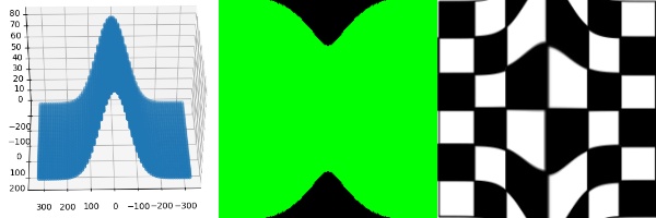
If you did not understand the above steps, don’t worry. We will explain each step in detail.
Creating a virtual camera
Based on the above mentioned theory we clearly know how a 3D point is related to its corresponding image coordinates.
Let us now understand what a virtual camera means and how to capture images with this virtual camera.
Virtual camera is essentially the matrix P because it tells us the relation between 3D world coordinates and the corresponding image pixel coordinates. Let’s see how we can create our virtual camera using python.
We will first create the extrinsic parameter matrix (M1) and the intrinsic parameter matrix (K) and use them to create the camera projection matrix (P).
import numpy as np

# Defining the translation matrix
# Tx,Ty,Tz represent the position of our virtual camera in the world coordinate system
T = np.array([[1,0,0,-Tx],[0,1,0,-Ty],[0,0,1,-Tz]])

# Defining the rotation matrix
# alpha,beta,gamma define the orientation of the virtual camera

Rx = np.array([[1, 0, 0], [0, math.cos(alpha), -math.sin(alpha)], [0, math.sin(alpha), math.cos(alpha)]])

Ry = np.array([[math.cos(beta), 0, -math.sin(beta)],[0, 1, 0],[math.sin(beta),0,math.cos(beta)]])

Rz = np.array([[math.cos(gamma), -math.sin(gamma), 0],[math.sin(gamma),math.cos(gamma), 0],[0, 0, 1]])

R = np.matmul(Rx, np.matmul(Ry, Rz))

# Calculating the extrinsic camera parameter matrix M1
M1 = np.matmul(R,T)

# Calculating the intrinsic camera parameter matrix K
# sx and sy are apparent pixel length in x and y direction
# ox and oy are the coordinates of the optical center in the image plane.
K = np.array([[-focus/sx,sh,ox],[0,focus/sy,oy],[0,0,1]])

P = np.matmul(K,RT)
Note that you have to set suitable values for all the parameters in the matrix above, like focus, sx, sy, ox, oy etc.
Refer to this post to decide the focal length and this post to get an idea to set the other intrinsic and extrinsic parameters for the virtual camera.
So how do we capture images with this virtual camera?
First, we assume the original image or video frame to be a plane in 3D. Of course, we know that the scene is actually not a plane in 3D, but we do not have depth information for every pixel in the image. So, we simply assume the scene to planar. Remember, our goal is not to accurately model a funny mirror for a scientific purpose. We simply want to approximate it for entertainment.
Once, we have defined the image as a plane in 3D, we can simply multiply the matrix P to the world coordinates and get pixel coordinates ![]() . Applying this transformation is the same as capturing the image of the 3D points using our virtual camera!
. Applying this transformation is the same as capturing the image of the 3D points using our virtual camera!
How do we decide the color of pixels in our captured image? What about the material properties of objects in the scene?
All the above points are definitely of importance when rendering a realistic 3D scene, but we do not have to render a realistic scene. We simply want to make something that looks amusing.
All we need to do is capture (project) to first represent the original image (or video frame) as a 3D plane in the virtual camera, and then project every point on this plane onto the image plane of the virtual camera using the projection matrix.
So how do we do it ? The naive solution to to use a nested for loop and loop over all the points and perform this transformation. In python, this is computationally expensive.
Hence we use numpy to do such calculations. As you may know, numpy allows us to perform vectorized operation and removes the need to use loops. This is computationally very efficient than using a nested for loop.
So we will store the 3D coordinates as a numpy array (W), store the camera matrix as a numpy array (P) and perform a matrix multiplication P*W to capture the 3D points.
That’s it!
Before we write the code to capture a 3D surface using a virtual camera we first need to define the 3D surface.
Defining a 3D surface (the mirror)
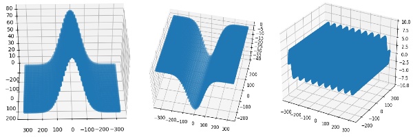
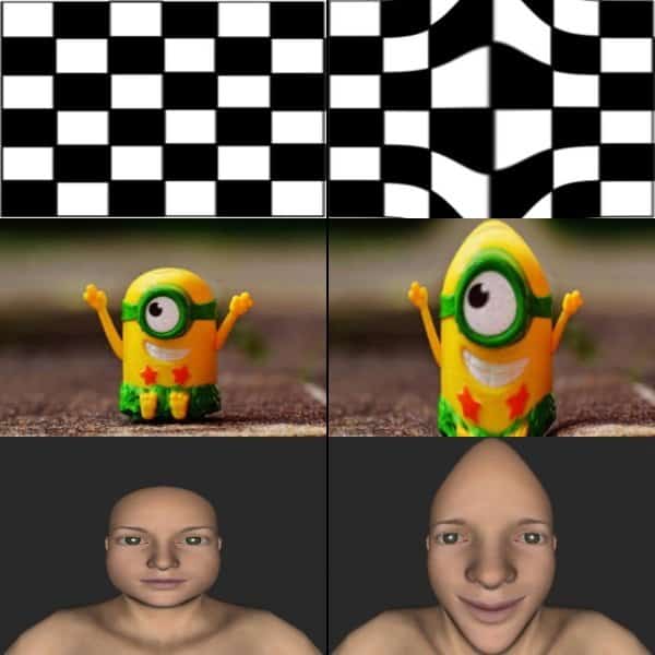
To define a 3D surface we form a mesh of X and Y coordinates and then calculate the Z coordinate as a function of X and Y for each point. Hence for a plane mirror we will define Z = K where K is any constant. The following figures show some examples of mirror surfaces that can be generated.
Now, as we have a clear idea of how to define a 3D surface and to capture it in our virtual camera, let’s see how to code it in python.
# Determine height and width of input image
H,W = image.shape[:2]
# Define x and y coordinate values in range (-W/2 to W/2) and (-H/2 to H/2) respectively

x = np.linspace(-W/2, W/2, W)
y = np.linspace(-H/2, H/2, H)

# Creating a mesh grid using the x and y coordinate range defined above.
xv,yv = np.meshgrid(x,y)

# Generating the X,Y and Z coordinates of the plane
# Here we define Z = 1 plane
X = xv.reshape(-1,1)
Y = yv.reshape(-1,1)
Z = X*0+1 # The mesh will be located on Z = 1 plane

pts3d = np.concatenate(([X],[Y],[Z],[X*0+1]))[:,:,0]

pts2d = np.matmul(P,pts3d)
u = pts2d[0,:]/(pts2d[2,:]+0.00000001)
v = pts2d[1,:]/(pts2d[2,:]+0.00000001)
This is how we generate the 3D surface which acts as our mirror.
VCAM : Virtual Camera
Do we need to write the above code every time ? What if we want to change some parameters of the camera dynamically ? To simplify the task of creating such 3D surfaces, defining a virtual camera, setting all the parameters, and finding their projection we can use a python library called vcam. You can find various illustrations of different ways in which you can use this library in its documentation. It reduces our efforts of creating a virtual camera every time, defining 3D points and finding the 2D projections. Moreover the library also takes care of setting suitable values of intrinsic and extrinsic parameters and handles various exceptions, making it easy and convenient to use. Instructions to install the library are also given in the repository.
You can install the library using pip.
pip3 install vcam
Here is how you can use the library to write a code that works similar to the code we have written till now but with just a few lines.
import cv2
import numpy as np
import math
from vcam import vcam,meshGen

# Create a virtual camera object. Here H,W correspond to height and width of the input image frame.
c1 = vcam(H=H,W=W)

# Create surface object
plane = meshGen(H,W)

# Change the Z coordinate. By default Z is set to 1
# We generate a mirror where for each 3D point, its Z coordinate is defined as Z = 10*sin(2*pi[x/w]*10)
plane.Z = 10*np.sin((plane.X/plane.W)*2*np.pi*10)

# Get modified 3D points of the surface
pts3d = plane.getPlane()

# Project the 3D points and get corresponding 2D image coordinates using our virtual camera object c1
pts2d = c1.project(pts3d)
One can easily see how vcam library makes it easy to define a virtual camera, to create a 3D plane and also to project it in the virtual camera.
The projected 2D points can now be used for mesh based remapping. This is the final step to create our funny mirror effect.
Image remapping
Remapping is basically generating a new image by shifting each pixel of the input image from its original location to a new location defined by a remapping function. Thus mathematically it can be written as follows :
![]()
The above method is called forwards remapping or forward warping, where map_x and map_y functions give us the new location of the pixel, which was originally at (x,y).
Now what if map_x and map_y do not give us an integer value for a given (x,y) pair? We spread the pixel intensity at (x,y) to the neighbouring pixels based on the nearest integer values. This creates holes in the remapped or resulting image, pixels for which the intensity is not known and is set to 0. How can we avoid these holes ?
We use inverse warping. Which means now map_x and map_y will give us the old pixel location, in the source image, for a given pixel location (x,y) in the destination image. It can be expressed mathematically as follows:
![]()
Great ! we now know how to perform remapping. To generate the funny mirror effect we will be applying remapping to the original input frame. But for that we need map_x and map_y right? How do we define map_x and map_y in our case? Well we have already computed our mapping functions.
The 2D projected points (pts2d), equivalent to (u,v) in our theoretical explanation, are the desired maps that we can pass to the remap function. Now let’s see the code to extract maps from the projected 2D points and applying the remap function (mesh based warping) to generate the funny mirror effect.
# Get mapx and mapy from the 2d projected points
map_x,map_y = c1.getMaps(pts2d)

# Applying remap function to input image (img) to generate the funny mirror effect
output = cv2.remap(img,map_x,map_y,interpolation=cv2.INTER_LINEAR)

cv2.imshow("Funny mirror",output)
cv2.waitKey(0)
Awesome ! Let’s try to create one more funny mirror to have a better idea. After this you will be able to make your own funny mirrors.
import cv2
import numpy as np
import math
from vcam import vcam,meshGen

# Reading the input image. Pass the path of image you would like to use as input image.
img = cv2.imread("chess.png")
H,W = img.shape[:2]

# Creating the virtual camera object
c1 = vcam(H=H,W=W)

# Creating the surface object
plane = meshGen(H,W)

# We generate a mirror where for each 3D point, its Z coordinate is defined as Z = 20*exp^((x/w)^2 / 2*0.1*sqrt(2*pi))

plane.Z += 20*np.exp(-0.5*((plane.X*1.0/plane.W)/0.1)**2)/(0.1*np.sqrt(2*np.pi))
pts3d = plane.getPlane()

pts2d = c1.project(pts3d)
map_x,map_y = c1.getMaps(pts2d)

output = cv2.remap(img,map_x,map_y,interpolation=cv2.INTER_LINEAR)

cv2.imshow("Funny Mirror",output)
cv2.imshow("Input and output",np.hstack((img,output)))
cv2.waitKey(0)
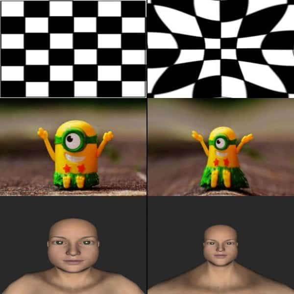
So now as we know that by defining Z as a function of X and Y we can create different types of distortion effects. Let us create some more effects using the above code. We simply need to change the line where we define Z as a function of X and Y. This will further help you to create your own effects.
# We generate a mirror where for each 3D point, its Z coordinate is defined as Z = 20*exp^((y/h)^2 / 2*0.1*sqrt(2*pi))

plane.Z += 20*np.exp(-0.5*((plane.Y*1.0/plane.H)/0.1)**2)/(0.1*np.sqrt(2*np.pi))

Let’s create something using sine function !
# We generate a mirror where for each 3D point, its Z coordinate is defined as Z = 20*[ sin(2*pi*(x/w-1/4))) + sin(2*pi*(y/h-1/4))) ]

plane.Z += 20*np.sin(2*np.pi*((plane.X-plane.W/4.0)/plane.W)) + 20*np.sin(2*np.pi*((plane.Y-plane.H/4.0)/plane.H))
How about some radial distortion effect ?
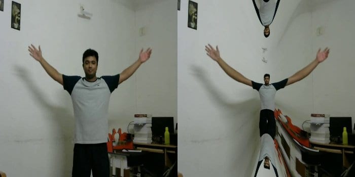
# We generate a mirror where for each 3D point, its Z coordinate is defined as Z = -100*sqrt[(x/w)^2 + (y/h)^2]

plane.Z -= 100*np.sqrt((plane.X*1.0/plane.W)**2+(plane.Y*1.0/plane.H)**2)

This post is inspired by the fun mirrors repository. You can find various other interesting funny mirrors shared there. There are also some challenges where the solution to generate the funny mirrors is not provided and you need to apply your mathematical and creative thinking skills to get the solution.
Go ahead and create your own mirrors and share it with your loved ones. The number of different mirrors you can create is now only constrained to how creative you can be and how well you can visualize mathematics.








100K+ Learners
Join Free OpenCV Bootcamp3 Hours of Learning